
The OSI Model (Open Systems Interconnection Model) was developed by the International Organization for Standardization (ISO) in 1984.
It is a conceptual framework. You can think of it as a rule book, that describes how data should travel from one computer application to another application of second computer over a network, regardless of the hardware or software involved.
This is similar to the example below.
Example 1 – Suppose, you send the message “Hello” from your phone to your friend’s phone, using WhatsApp.
Step-by-Step Journey
- You type “Hello” and press Send. (Application layer)
- WhatsApp encrypts messages. (Presentation Layer)
- The Session layer establishes, and maintains the connection session.
- The transport layer breaks it into smaller pieces, if necessary.
- The network layer adds the source and destination IP addresses.
- The data link layer adds the MAC addresses.
- The physical layer transmits bits through Wi-Fi or mobile data.
- On the receiver side, the process occurs in the reverse order and your friend sees “Hello” on the screen.
Example 2 – Loading a website
When compgeek.co.in is opened in a web browser.
- Application Layer – The browser requests the webpage.
2. Presentation Layer – Data may be encrypted using HTTPS.
3. Session Layer – Connection session is maintained.
4. Transport Layer – TCP ensures reliable delivery.
5. Network Layer – IP routing sends packets across the Internet.
6. Data Link Layer – Frames travel between routers and devices.
7. Physical Layer – Signals travel through cables, fiber optics, or wireless networks.
The model divides the entire communication process into 7 distinct layers, and each layer has a specific job to do.
No layer interferes with another’s job. This is called separation of concerns.
No layer interferes with another layer’s job. This is called separation of concerns. It is a principle you will encounter again and again in computer science.
.
How to Remember the 7 Layers
Students often use a memory trick. Reading from Layer 7 (top) down to Layer 1 (bottom).
In hindi, it is “Archimedes पानी से तत्काल नंगे पाँव दौड़ पड़े” (Archimedes Paani Se tatkal nange daud pade).
Archimedes discovered an important principle while bathing and excitedly ran through the streets shouting, “Eureka!” (“I have found it!”).
.
In english, it is “All People Seem To Need Data Processing”
A – Application, P — Presentation, S — Session, T — Transport, N — Network, D — Data Link, P — Physical
Or from bottom to top “Please Do Not Throw Sausage Pizza Away”
.
LAYERS from Top to Bottom
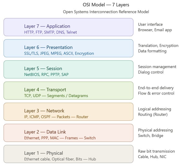
Application Layer – Layer 7
Think of this layer as the receptionist at a company. When you walk into an office, the receptionist is the first person you interact with. In the same way, the Application Layer is the first layer you interact with when you use a computer program to communicate over a network.
This layer means the protocols and rules that allow software to communicate. When you type www.google.com in your browser, the browser uses HTTP (HyperText Transfer Protocol) to talk to Google’s server. HTTP is an Application Layer protocol.
Key protocols at this layer –
Protocol | Full Form | Purpose |
HTTP | HyperText Transfer Protocol | Used to transfer web pages between a web browser and a web server. |
HTTPS | HyperText Transfer Protocol Secure | A secure version of HTTP that encrypts communication using SSL/TLS. |
FTP | File Transfer Protocol | Used to upload and download files between computers over a network. |
SMTP | Simple Mail Transfer Protocol | Used to send emails from a client to a mail server or between mail servers. |
POP3 | Post Office Protocol Version 3 | Used to receive and download emails from a mail server to a local device. |
IMAP | Internet Message Access Protocol | Used to access and manage emails directly on the mail server. |
DNS | Domain Name System | Converts domain names (such as www.google.com) into IP addresses. |
Telnet | Telecommunication Network | Provides remote access to another computer, but data is transmitted in plain text. |
SSH | Secure Shell | Provides secure remote access to another computer using encryption. |
.
Presentation Layer – Layer 6 (The Translator)
This layer is like a translator at the United Nations. Imagine diplomats from 100 countries attending a meeting. Everyone speaks their own language. A translator converts every speech into a common language so that everyone understands. Similarly, the Presentation Layer converts data into a format that both sender and receiver can understand.
Key protocols at this layer –
Protocol/Technology | Purpose |
Translation | Converts data from one format to another so that different systems can understand and process it correctly. |
Encryption / Decryption | Encrypts (scrambles) data before transmission and decrypts (unscrambles) it after reception to ensure data security and confidentiality. |
Compression | Reduces the size of data before transmission to save bandwidth and improve transmission efficiency. |
.
Session Layer – Layer 5 (The Meeting Organizer)
Have you ever been on a video call and noticed how the call starts, continues, and then formally ends? Someone has to manage that session. The Session Layer does exactly that for network communication.
When two computers want to communicate, a session (a temporary connection) must be established, maintained, and terminated properly. Without this, data would arrive without any structure. Sessions also handle checkpointing, if a large file transfer fails in middle, the session layer can resume from where it stopped rather than restarting.
Key protocols at this layer –
Protocol/Technology | Purpose |
NetBIOS (Network Basic Input/Output System) | Establishes and manages communication sessions between computers on a network. |
RPC (Remote Procedure Call) | Allows a program on one computer to execute a procedure on another computer. |
PPTP (Point-to-Point Tunneling Protocol) | Creates VPN connections by establishing secure communication sessions. |
SMB Session Service (Server Message Block) | Manages file-sharing and printer-sharing sessions between network devices. |
SAP (Session Announcement Protocol) | Announces and describes multimedia sessions on a network. |
.
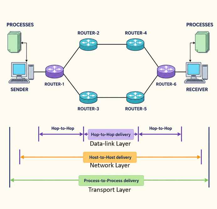
Transport Layer – Layer 4 (The Courier)
This is one of the most important layers and demands careful attention from every student. The Transport Layer is responsible for end-to-end communication between two computers. Not computer to router, not router to router, but from the source application all the way to the destination application. It adds a header to the segment (data).
The two most important protocols here are TCP and UDP, and understanding the difference is something every interviewer, every exam paper, and every real-world engineer will ask you about.
.
Key protocols at this layer –
TCP (Transmission Control Protocol) – is like a speed post service. When you send a speed post letter, you get a receipt, the recipient signs upon delivery, means end-to-end communication and TCP does the same.
TCP establishes a connection using a three-way handshake (SYN → SYN-ACK → ACK), numbers every piece of data (segment), confirms delivery with acknowledgements, and retransmits if something is lost. It is reliable but slower. Also is used for web browsing, email, file transfer.
UDP (User Datagram Protocol) – is like throwing pamphlets from a helicopter. You throw them and don’t care who picks them up. There is no handshake, no acknowledgement, no retransmission. It is fast but unreliable, and is used for live video streaming, online gaming, DNS queries, voice calls.
Other important functions of the Transport Layer is
1. Port numbers – to identify which application the data belongs to
2. Flow control – is the process of regulating data transmission so that, the sender does not transmit data faster than the receiver can process it.
3. Error detection – checks whether the received data is the same as the data sent by the sender.
.
Network Layer – Layer 3 (The Router)
If the Transport Layer is the courier company, the Network Layer is the GPS navigator. Its job is to determine the best path for data to travel from source to destination across multiple networks.
IP address – To understand how devices communicate over the Internet, we first need to understand the concept of an IP address. Every device on a network has a unique IP address, just like every house has a unique postal address.
Packet – The data unit at this layer is called a packet. The network layer adds a header to the packet containing the source IP address and destination IP address.
Routers – The devices that work at this layer are Routers. A router reads the IP address on each incoming packet and decides which direction to forward it. This decision is made using a routing table — a map that the router maintains internally. Routing protocols like OSPF, BGP, and RIP help routers build and update these maps.
IP (Internet Protocol) is the most important protocol here. ICMP (Internet Control Message Protocol) used by the ping command also is in this layer.
.
Data Link Layer – Layer 2 (Delivery Guy)
If the Network Layer handles routing across multiple networks, the Data Link Layer handles communication within a single network between two directly connected devices. It is like a delivery guy, if my package comes from the Kerala and I am living in Delhi. There are several delivery guys from the source (where the package packs) to destination (my home).
The data unit here is called a Frame. The Data Link Layer adds a MAC address (Media Access Control address) header to the data and a trailer too for error detection information. A MAC address is a hardware address permanently burned into every Network Interface Card (NIC). Unlike IP addresses which can change, MAC addresses are fixed.
This layer has two sublayers
- LLC (Logical Link Control) — handles error checking and flow control
- MAC (Media Access Control) — handles how devices share the physical medium
The key device at this layer is a Switch. A switch reads the MAC address of incoming frames and forwards them to the correct port. This is different from a router, which works with IP addresses.
Key protocols at this layer –
Protocol | Purpose |
Ethernet | Provides wired communication within a Local Area Network (LAN). |
PPP (Point-to-Point Protocol) | Establishes direct communication between two network devices. |
Wi-Fi (802.11) | Provides wireless communication within a Local Area Network (LAN). |
.
Physical Layer – Layer 1
This is the foundation, the bottom of the model. The Physical Layer deals with the actual physical transmission of raw binary data (0s and 1s) over a physical medium.
It is not concerned with meaning, structure, or addressing. It only asks one question. How do we send bits from point A to point B?
Physical Layer Feature | Description |
Physical Medium | Defines the transmission medium, such as copper wire (UTP cables), optical fiber, or wireless radio waves. |
Signal Types | Defines how data is carried using electrical signals, light pulses, or radio waves. |
Bit Rate | Specifies how many bits can be transmitted per second. |
Connector Types | Defines the physical connectors used for communication, such as RJ-45 and fiber-optic connectors. |
Encoding Schemes | Defines how binary data (0s and 1s) is represented as signals, such as Manchester encoding. |
Devices at this layer – Hub, Repeater, Modem, Network cables, NIC (Network Interface Card).
.
How Data Flows — Encapsulation and Decapsulation
This is the most critical concept to understand after the layers themselves.
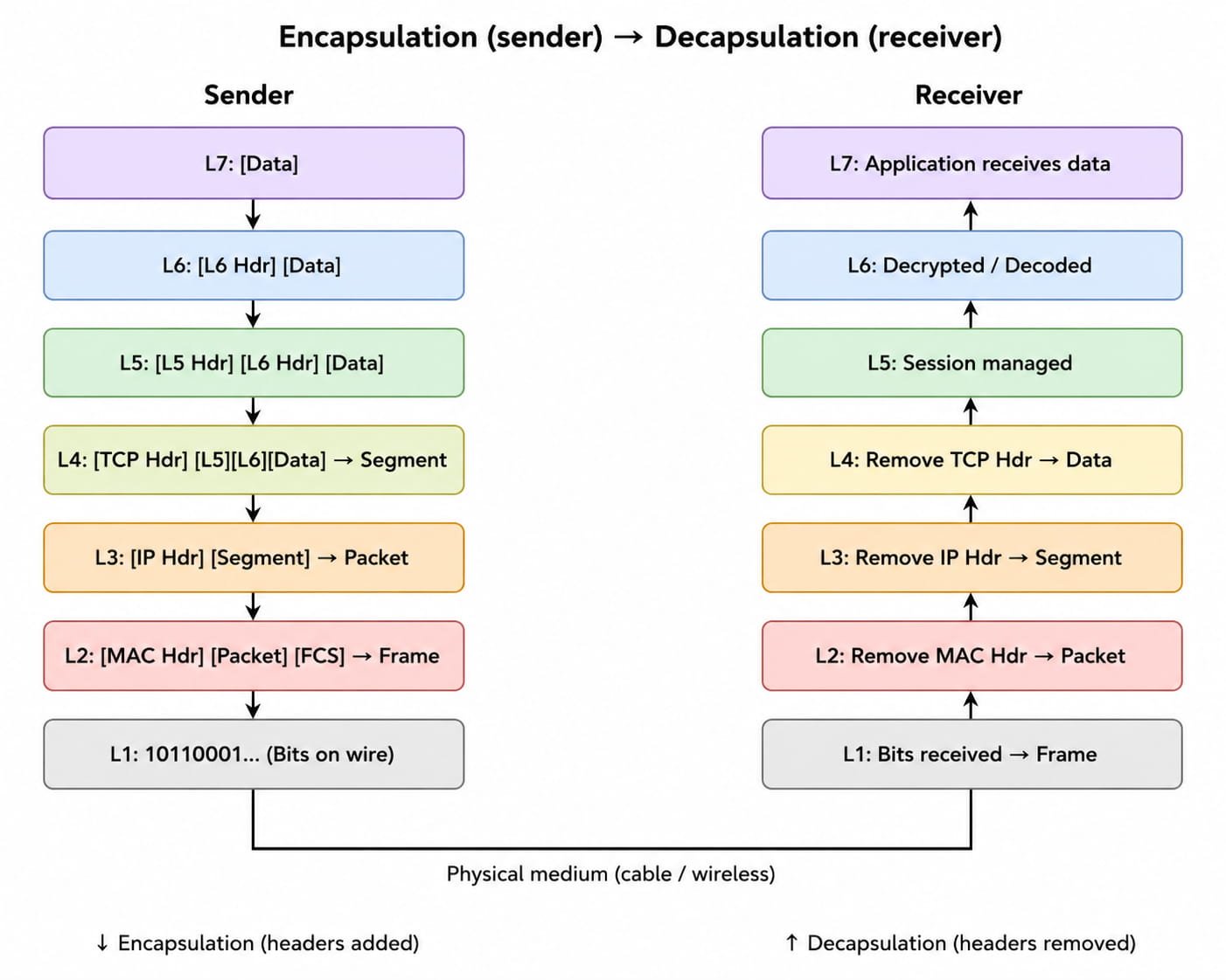
Encapsulation – When you send data, each layer at the sender’s side adds its own header and datalink layer adds a trailer too to the data before passing it down. This is called encapsulation.
.
Decapsulation – When the data arrives at the receiver, each layer removes its own header and passes the remaining data up. This is called decapsulation.
BOOKS